Feature Story Explosion protection in separators Safety at 12,000g
페이지 정보
작성자 최고관리자 댓글 0건 조회 1,418회 작성일 22-09-15 19:29본문
The forces that act on separators are powerful. Safety is therefore the top priority for Flottweg. First of all, the focus is on the materials. Only high-quality, wear-resistant components are used in the separators, which the Vilsbiburg-based company develops and produces entirely in Germany.
The process itself is subject to particular monitoring because of the powerful acceleration. The product to be clarified flows into the bowl via an infeed pipe. This is where the distributor gently accelerates it to full speed. The disc stack in the bowl separates the product stream into many thin layers, thereby creating a large surface area. The centrifugal force separates the solid material from the liquid inside the disc stack and deposits it at the edge of the bowl. The separated solid particles are periodically ejected at maximum speed via a hydraulic system in the lower part of the bowl. The clarified liquid flows out of the disc stack into a centripetal pump and is discharged under pressure.
All safety parameters are controlled by a programmable logic controller. An automatically monitored lubricant supply ensures that the drive is safe. The Soft Shot emptying system plays a key role in protecting the operator. It can lower the sound pressure level during partial and full discharges to such an extent that the separator does not require any special noise protection measures.
Explosion protection for processes, sensors and motors
Explosion protection warrants particular attention because there is a risk of explosion when processing combustible products. With closed containers, for example, there is the option to use inertisation, which prevents oxygen from entering the system as part of the ambient air. However, this alone is not enough. All additional external electrical and non-electrical components required for the separators to function correctly must fulfil specifications for explosion protection too. Equipment manufactured to be explosion-protected is used for sensors, drive motors and control valves. However, converting the main control system for use in a hazardous area requires a unique approach.
A look at the main control system
Flottweg did not want to deviate from their own products for the complex main control system. Here, an explosion protection solution had to be found that suited the limited space available, whilst also complying with the strict requirements of the control system. Initially, conversion using several Ex d enclosures was considered. However, Ex d enclosures have limited dimensions, meaning a large number of bushings would be necessary. Furthermore, the power dissipation of the main control system could not be controlled with Ex d enclosures.
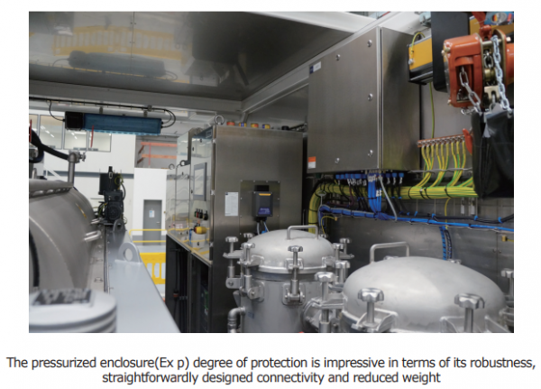
R. STAHL brought the "Ex p protection through pressurized enclosure" type of protection to the table, additionally suggesting the Ex p control panel as a solution. The Ex p system can be used in gas hazardous areas in Zones 1 and 2.
Ex p systems offer clear advantages – these solutions save space and are easy to connect. R. STAHL offers various design sizes, ensuring sufficient space is available for additional components. Ex p systems feature improved flow technology, which significantly reduces the necessary supply of compressed air and lowers energy costs.
Three steps to safe use
The Ex p control and monitoring systems always consist of an Ex p control unit, Ex p pressure monitors and Ex p purge valves with digital and proportional control. Based on time intervals and pressure analyses, the purge valves automatically control and transport ignition protection gases, such as compressed air, into the inside of the Ex p enclosure. Additionally, a temperature monitoring and control system is integrated inside the enclosure to provide adequate cooling.
Typical Ex p pressurized enclosures are operated in three separate steps:
Preparation phase: Compressed air or inert gases are transported into the Ex p enclosure via the purge valve and an overpressure is generated. Once this is achieved, the "pre-purging" phase begins; this is regulated via the Ex p control unit.
Pre-purging phase: Before starting up the equipment located inside the cabinet, any explosive mixture that may be present must be removed from the enclosure. The purge valve opens once the preset internal enclosure pressure has been reached. Next, thorough purging is performed using ignition protection gas that flows through the additional opening in the air outlet valve. These air outlet valves(pressure monitors) are positioned in different locations in order to guarantee controlled flow behaviour. The extremely short purge times at very low pressure loads(0.002 bar) are particularly advantageous. This enables the wall thickness of the cabinet walls to be reduced to less than 2 mm. This, in turn, lowers costs. Once the pre-purging phase is complete, the purge valve closes and the purge flow stops. The internal enclosure pressure returns to the preset value and the air outlet valve closes.
Operating phase: Normal operation begins and the control unit monitors and regulates the internal enclosure pressure in order to prevent explosive gases or dusts from entering the enclosure. The purge valve automatically compensates for any leakage losses.
Adapted to the application
The wishes of Flottweg employees were taken into account by developing application-specific solutions. For example, the doors on the cabinet, which were originally permanently installed, were judged to be a great hindrance for service work during operation. This resulted in a housing assembly with detachable doors that can also be securely reattached even if the housing chamfer is not visible. A specially developed positioning aid for the doors ensures that they close securely, even when the internal pressure is slightly increased during the pre-purging phase.
Service-friendly air conditioning
Industrial temperature control devices have also been installed. Based on an assessment during base load operation and emerging sporadic peaks, the decision was made to use two different air conditioning systems. A "normal" air conditioner has been installed in the roof wall to control the base load. With these devices, the outer circuit is designed to be suitable for Ex Zone 1, while the inner circuit and control system are part of the Ex p control panel. As a result, industry-oriented components that are simply more service-friendly for practical everyday use can be utilised.
In addition, vortex cooling has been installed to deal with sporadic peak loads. This does not have any movable components and generates a cold airflow solely by rotating the air and separating it into a cold and warm airflow. The cold airflow(up to +5 °C) is used for additional cooling for the Ex p control panel. The relatively simple usage of vortex cooling makes it possible to integrate temperature regulation into the type 8621/1 Ex p system. The two existing Ex i terminals have been used here, which evaluate the signal from an internal thermometer and activate additional cooling via the purge valve with downstream vortex coolers.
Keep a safe eye on all parameters
In addition, during the development of the Ex p control panel, particular care was taken to ensure that both our own explosion-protected HMIs and also non-explosion-protected operating terminals can be used in the door. Consequently, the operating terminals generally used by Flottweg can also be used in this Ex system without having to undergo expensive approval procedures.
Conclusion
More and more users are deciding to use pressurized enclosures(Ex p) as a degree of protection, since they are particularly impressive in terms of their robustness, straightforwardly designed connectivity and reduced weight. This not only makes a safe solution possible – a pressurized enclosure also offers economic and functional benefits. At Flottweg, the simple integration of air conditioning ultimately tipped the scales in favour of designing the overall control system as a pressurized application. The specialists at R. STAHL were able to implement a safe configuration for both sides using this solution, which is also suitable for worldwide use.
■ Contact: R. STAHL www.r-stahl.com

